| Data name |
| Clamp strain and chatter prevention by vacuum chuck |
| Overview |
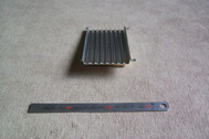
| This work uses a vacuum chuck since it is difficult to satisfy the surface
roughness or attain machining accuracy, because the remaining plate thickness
after R4 ball end mill processing is as thin as 0.5mm. Processing number:8/spot |
 |
| Point |
| クClamp distortion, vibration and working strain were solved by vacuum chuck, and it improved machining accuracy. ・A5052 |
| Result |
| There was no vibration or clamp, processing distortion at all, and processing has fineshed without any problems. Machining accuracy was attained with variations in thickness direction of less than5μ. |
| Commentary |
| We sometimes use adhesives/ bonds for processing materials that are thin, or have complicated shapes, but since it takes time pre-treating and after-treating, we used a vacuum chuck this time. The machining of the back surface was conducted as the first step in this work, followed by the cutting of the contour up to the depth of 4.5mm by plane, and the rest of the surface was processed in the second step. The mounting base is used for both sides and for the surface machining. By using the vacuum chuck, the base and the work became metal touch without floating in the thickness direction, the rigidity of the work increasing, the chattering disappearing, and the machining accuracy markedly improving. As a result, the remaining dimensional difference of 0.5mm from the bottom of the ball end mill was contained to 5μ or less. Vacuum chucks do not require the skill for clamping because the work can be uniformly held without changing of the clamping force by the operator. The tools used in this case such as end mills, ball end mills, face milling cutters are commercially available. No special items are used. |
| Comment |
| In most cases in which a vacuum chuck is used for a milling/ machining center, the mounting base is specified for the workpiece. Since the clamping force of the vacuum chuck, when applied in the horizontal direction, is about 35% of the clamping force of the vertical direction, the stopper is made in the X and Y direction in the base. The O-ring groove for preventing leakage, and the leak groove for improvement of exhaust performance are processed in the base. 今This time, the base was made of aluminum to improve the heat dissipation of the workpiece. Machining of the base was done with a machine that processes the workpiece. Machining is conducted under the same conditions as those cases with plate thickness. |
 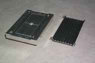  Base and work |